This was nothing short of a blunder on our part; a failure in a tube-to-tube sheet joint is virtually inconceivable for a company that specializes in shell-and-tube heat exchangers.
Was the design of the tube-to-tube sheet joint faulty? It did not seem so; it was as per the order specifications and datasheet. It had two rounded grooves with full length hydraulic expansion and a seal weld-run. (refer to Figure-1 below)
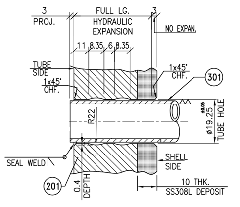
Tube Material: SA 213 TP 304L, Size:19.05OD x 2.77 THK. (AVG)
Tubesheet Material: SA 765 Gr II, 300 THK.
Figure-1: Tube-to-Tubesheet Joint Detail
So, what could have gone wrong? The pull-out test failed several times and the client was upset at the slow progress. The work on the tube bundle came to a grinding halt, awaiting the reliability factor (Fr) results of the test. We resorted to jugaad (innovation with available resources) to get the desired results. However, there was something unusual about the expansion grooves that are usually rectangular with corners that allow active tube material to flow when expanded. But here the grooves were rounded with shallow concave curves. Our failure was not so much in not noticing this as it was in not facing up to the client. We were pushed to the wall and our pleas were firmly disregarded. We had no choice but to follow their datasheet strictly, though this was akin to putting the wool over our eyes. We hoped against hope that everything would work out.
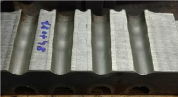
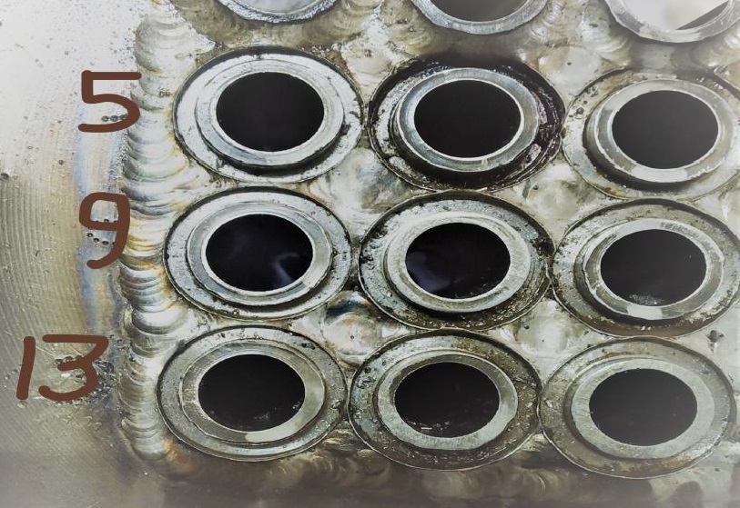
Figure-2: Polished cross section of TTJ mock-up
The manufacturing was completed and the shell-side hydrostatic test was faultless. All the same, on applying the tube-side pressure – which was much higher than the shell-side pressure – the result was disastrous. Leakage occurred even before we could attain the full pressure; water trickled out of the shell nozzle.
To identify the source of the leak in the bundle, we pulled out the shell after removing the bolts. As expected, the leakage was not from the tubes, but from the tube-to-tube sheet joints. To locate these joints, we raised the pressure in the expectation that the faulty joints would burst open. This went on for days. Subsequently, we dismantled the channel, buttoned up the shell side and pressurised the shell with helium to locate the faulty joints. We found most joints leaky.
While these were being repaired, we took a firm stand with our client and decided on a detailed study by conducting sufficient tube-to-tube sheet mock-ups. Extensive research was done after going through the mock-up results. We came to the conclusion that a strength weld was required along with the full length of the tube-to-tube sheet expansion. The shallow grooves placed close to the back end of the tubesheet were meant to seal the passage of shell fluid and avoid contact with any part of the joint. In this joint, the expansion and the grooves acted as the sealant, while the weld provided strength.
The licensor was concerned as the end-user had complained about our inability to manufacture this specialized equipment. We promptly sent them the case study and clarified our position indicating seal weld in the datasheet. The process licensor assumed that providing strength weld was unnecessary as two rounded grooves with full length hydraulic expansion was already specified. This was a gross error in their judgment and having put it up in their specifications it became a bible for the rest to follow.
With the equipment required urgently at the site, we were still under pressure. We did not want to make anything sub-standard. Our strong sense of ownership even after we have sold any equipment prevented us from doing so. We needed time for correction. We devised a cutter just fitting the outside diameter of the tube, with a Teflon bar fixed at the core. The annular gap between the core and the cutter was the same as the tube thickness. We ran several mock-ups with it.
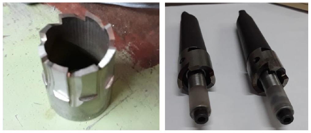
The idea was to make 3mm deep narrowest groove possible on the tube side face of tube-sheet. The narrow gap would ensure proper welding of the groove between the tube and tubesheet. Subsequent weld runs between the tube and the tubesheet made the size of the weld close to strength weld with a maximum leak-path. This was a difficult and time-consuming exercise we had to undertake at our expense, as the consultant was not in favour and the end-user wanted the equipment in a hurry, leaky or otherwise. They had already placed an order with another manufacturer for a replacement tube bundle to substitute ours.
We told them that the replacement bundle would fail if made as per their original specifications and if they were to change the specifications, a royalty was due to TEMA India. All said and done, the equipment went through the entire cycle of rework (undoing + doing) before being test stamped by the ASME-AI and the client. It has been working efficiently ever since.
Copyright © 2020 Haresh Sippy
(This article is subject to copyright.)