Gasket joints in pressure vessels
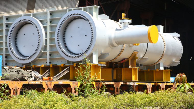
A shell-and-tube exchanger that needs overhauling has to be dismantled and buttoned up after servicing. This entails the opening and closing of joints designed for pressure and temperature. This is where engineering and experience come into play, and therefore the most challenging part of the entire design. There are several types of such joints we come across.
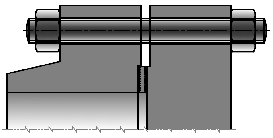
The conventional type is the flange joint, which has two mating flanges with gasket faces to house a gasket in between, with fasteners on the outside to clamp them and compress the gasket as a sealant. The load induced by the bolts must not only compress (seat) the gasket fully, but maintain the compression (seating) to counter the internal pressure as well. The clamping load depends on the gasket type and the amount of pressure it has to withstand.
The gasket material is selected to maximize the seating load and the strength against crushing. The width of the gasket has to be minimized to counter the maximum crushing load. In other words, the gasket has to be malleable, durable and uncrushable (high load-bearing capacity). The smaller the width of the gasket, the lighter will be the flanged joint.
Gasket width = Gasket Outside Diameter (GOD) – Gasket Inside Diameter (GID)
In this configuration, the bolts are on the outside i.e. Bolt Circle Diameter (BCD) > GOD. Greater the BCD as compared to GOD, the more cantilevered it will be. Longer the cantilever, the more rigid it has to be. Although the closer BCD is to GOD, the better, the difference between the two depends on the required clamping load [the size and the number of bolts (studs + nuts)]. Greater the number and size of bolts, higher the BCD. Higher the BCD, greater is the rigidity required. The optimum joint design is arrived by performing numerous iterations.
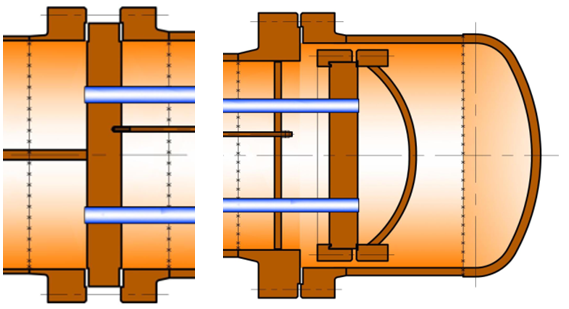
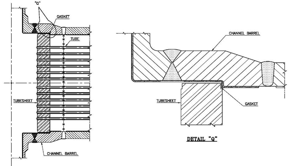
The tube-sheet sandwiching between two flanges must also be considered. This joint has two gaskets, one between the shell flange and tube-sheet, and the other between the tube-sheet and the channel flange. Both gaskets are compressed by a single set of fasteners. These are exposed to the atmosphere; the pressure is only internal. This apart, there are floating head-cover joints, which are inside the bonnet in connection with the main shell. These joints are subjected to the shell side (external) and the tube side (internal) pressure. The joints covered so far are commonly used and designed to specifications as per the code. Various programs are available to do their design.
Proprietary technology
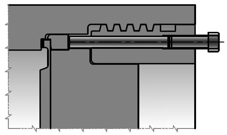
On the other hand proprietary gasket joints are not covered by codes and standards. The most critical among these is the one for screw-plug (breech-lock) heat exchangers, for which TEMA India holds a patent. In this case, BCD= (GOD-GID)/2. The source of compression of the gasket is directly at its centre, unlike in a flange, which is cantilevered. This is a unique design, is much more effective.
However, this being a proprietary design imposes the usual problems in the transfer of technology, the gasket between the tube-sheet and the shell has always been a nightmare for both the end-user and the manufacturer. We were the first to find the perfect solution. The lesson was learnt when six screw-plugs for the LOBS project of BPCL were found leaking in the year 2005. The gaskets had given way. These were spiral-wound gaskets as specified by the licensor Chevron. We replaced these with new ones that were supplied as spares, but the result was the same. We investigated and realized why they were getting crushed.
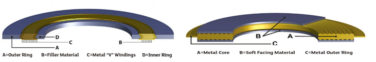
The spiral-wound gasket is rightfully specified and always used for this joint as it has the cushioning (recovery) required for a gasket face machined at a depth of more than a meter, where providing the required accuracy and surface finish was difficult. This gasket is malleable enough to adjust to the flaws in machining. As such all our earlier screw-plugs (breech-locks) supplied to Haldia, CPCL and BPCL refineries have had the spiral-wound gasket.
But in this particular case it did not work and we were sure that the Kamprofile gasket alone would. Kamprofile being a solid metal, the possibility of crushing doesn’t arise. However, it is not a specified gasket because it does not have any cushioning, and could cause significant leaks with such gasket faces. This is where TEMA India’s expertise comes into play, due to our special machining techniques. We were confident, but permission had to be sought from Chevron, who involved their expert David Reeves. All the data was sent to Chevron with our proposal and we tried our best to put across our point, but failed. Reeves insisted that we follow their specifications.
We were asked to meet the CMD of BPCL Refineries RK Singh, along with the project director, the Chief of Maintenance Mr. Chakravarti and a few others. Mr. Singh wanted to know what had gone wrong. We expressed our confidence in the Kamprofile gasket, they realized there was no other solution and so ours was accepted.
Everything worked out after that and till date there are no complaints. Years later we faced a similar situation in CPCL and HMEL where we had supplied a fresh set of Screw-plugs and with no deviation, from the Chevron specs with spiral-wound gaskets and the exchangers gave similar problems. Fortunately, we had tried convincing them to deviate from the specs and allow us to use Kamprofile in place of spiral-wound right at the design stage and everything was well documented. Unfortunately, ours is the only country in the world which does not trust their talent and are not willing to take a single step without the concurrence of the licensor sitting overseas.
We had a lot of convincing to do, we did a complete FEA to prove our point, and finally, we managed. As a result till this date, all our exchangers are giving trouble-free service world over.
I also presented a paper on the subject at an ASME annual conference. Today it has become a norm to use Kamprofile for such joints; even David Reeves recommends it.
Non-Oil & Gas proprietary processes
The client maybe the licensees or the end-users, but specifying the gasket joint is outside their ambit. They believe that TEMA should be able to manufacture equipment based on drawings given to other manufacturers, since such equipment is in running order. This statement has no logical bearing. Drawings don’t reveal technology; the standards do, and the manufacturing sequence to achieve the standards remain with the licensor. This is the norm with proprietary products. They are introduced under the exclusive legal right of the licensor, who has no obligation to divulge any information of its form or function, unless contractually obliged to do so.
A manufacturer is in the dark, unless the manufacturing standards are authorized and available, or access is provided to the licensor’s guidance. Failing which, it becomes a gamble to proceed.
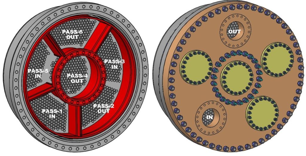
Recently, we executed an order where the heat exchangers had a unique spider-like pass partition design which divided the tube-layout into 6 zones- central core surrounded with 5 sectors. It was a challenging task to compress the four SPWD gasket rings simultaneously and uniformly with single channel cover (2540mm OD x 208mm Thk) by tightening 80 Nos. bolts located on two different PCDs.
For achieving the leak tightness at all the gasket joints, we carefully machined the gasket faces of mating components in one plane and followed a unique bolt tightening sequence. Considerable R&D was required, which is nothing but a trial and error process that involves time and resources.
Dealing with unknown gaskets
Recently, we executed an order for the manufacture and supply of eight large vessels, the design and drawings of which were given by the client (licensor) as free issue. The licensor experimented with a new gasket (Metallic Reinforced Glass-proofed Cloth) and flange design with full face gasket on very large obround openings and made us face uncertainties during the hydro test.
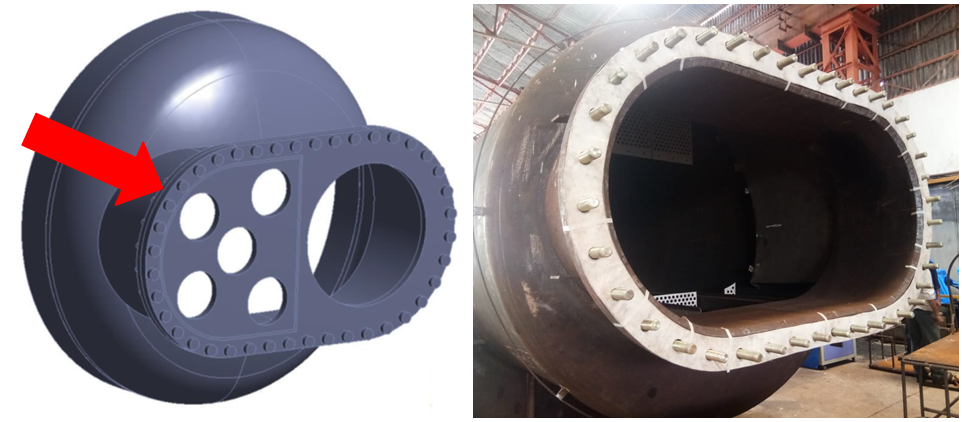
Figure 7: Large obround opening with full face gasket
The gasketed joints began to leak just after water fill-up, before pressurizing. The hydro test could not be cleared even after increasing the bolt load, retightening, tightening in multiple stages and changing the gasket. Every time the joint was opened, approximately 60,000 liters of hydro test water had to be drained out, resulting in a loss of time and money. The hydro test pressure was only 9.1 kg/cm2.
The new gasket specified on the drawings was not available in the Indian market. Our suggestion of using a CNAF gasket instead was not accepted. After prolonged discussions with gasket vendors, one of them agreed to supply the specified gasket. We got the gasket datasheet approved by the licensor before procurement. Using this gasket, the hydro test failed again.
Subsequently, the licensor recommended the application of High Temperature Gasket Silicon, and flanges to be clamped while the silicon was wet. These instructions were not specified on the client’s drawings. Nevertheless, the hydro test failed again. After repeated hydro test failures with gaskets procured by us, the client supplied the required gasket as FIM, but to no avail. The client’s lack of experience with this gasket and joint configuration was revealed when they suggested using a high-thickness gasket if the leakage persisted. The equipment cleared the hydro test only with the use of the CNAF gasket, as originally proposed by us.
Incorrect torque value
The torque values specified on the drawing for M42 bolts was 1200 N-m, significantly lower than the ASME PCC-1 recommended torque value of 3350 N-m. We proposed to tighten the bolts to 3300 N-m. The client disagreed and asked us to tighten it for 1600 N-m. When the joint continued to leak during the hydro test, they asked us to increase the torque to 1800 N-m, which was subsequently raised to 2100 N-m, 2400 N-m, 2800 N-m, 3000 N-m, and finally 3200 N-m, at which point the hydro test was cleared. Until then, the client made us conduct several hydro tests at the above-mentioned torque values, at the cost of several man hours of effort.
The licensor conducted experiments at the manufacturer’s cost and failed. Eventually, it was left to the manufacturer to diagnose the fault and set it right. In the event, we learnt a number of lessons. In the absence of familiarity with a gasket not widely used in the industry, procure a sample before commencing fabrication and test its leak-tightness on a small nozzle flange. Simply relying on the licensor’s recommendation can turn out to be a costly affair. This will reduce the possibility of error when the equipment is ready and few design changes can be made.
Lesson learnt:
SIMPLY RELYING ON LICENSOR RECOMMENDATION COULD BE COSTLY!
If you do not have prior experience for gasket which is not widely used in the industry, procure a sample of that gasket before start of fabrication and test its leak tightness for a small nozzle flange. This will save us from dealing with difficult situations when the equipment is already made and very few design changes can be made.
The moral of the story is the licensor conducted experiments at the manufacturers cost, all their experiments failed, and finally, the manufacture did the research at our cost, which was a success.
Copyright © 2020 Haresh Sippy
(This article is subject to copyright.)