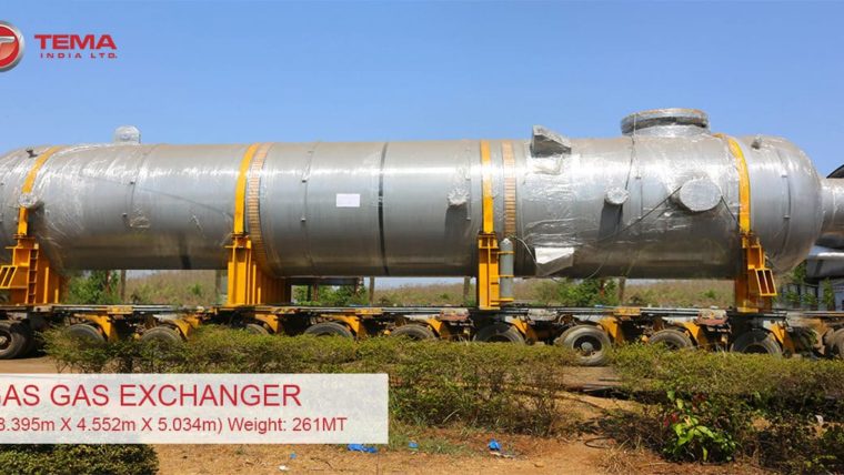
Introduction to Screw Plug exchangers
Screw Plug exchanger is a unique design which can contain fluids at ‘high pressure 200 bar (2900 psi)’ and ‘high temperature 500°C (932°F)’ with ‘small diameter bolts (bolt dia ≤ 2.5”)’ along with the ‘flexibility of bundle removal’ for cleaning. This makes them the preferred choice for ‘dirty services’.
Screw Plug exchangers are basically U-tube heat exchangers, and come in two constructions: Hi-Hi and Hi-Lo. In both constructions, the channel cover (plug) is screwed into channel barrel and typically, the tube side pressure is greater than shell side pressure.
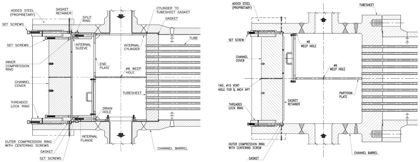
Figure 1: Hi-Hi Screw Plug construction (left), Hi-Lo Screw Plug construction (Right)
Hi-Hi construction
In this construction, the tube bundle is designed for a differential pressure below 50 bar (725 psi) which is less than the shell side and tube side design pressures.
The channel barrel is integral (welded) with the main shell eliminating external gasketed joints between the tubesheet and girth flanges of shell and channel. The tubesheet is internally sealed (gasketed) at an annular shoulder between shell and channel.
In this construction, the tube bundle can be pulled out for maintenance without disturbing the high pressure pipelines which is a major time saving during maintenance.
Hi-Lo construction
In this construction, the tubesheet is integral with channel (welded or single-piece drum forging) and bolted to low pressure (Ps < 70 bar) shell with conventional body flange.
Challenges faced by end users
All screw-plug/ breech-lock heat exchangers are ordered and manufactured in compliance with Licensor’s specifications, international construction codes and standards. There are several instances of exchangers supplied in full compliance with specifications failing in service- ‘jamming’ and ‘intermixing’ issues. This indicates that there are some finer aspects in design and manufacturing of these exchangers that are beyond the scope of codes and specifications. Therefore, compliance with specifications alone cannot be the measure of equipment quality!
Jamming of threaded plug due to bell-mouthing of threaded region of channel
At times, some end users have faced great difficulties in opening the threaded closures during the shutdowns. In such situations, they are compelled to resort to undesirable measures like heating the threaded end of channel using electrical resistance heating pads for several hours, applying dry ice packs on the inside diameter of threaded lock ring while applying high lock-breaking torque with crane, vibrating threaded region of channel barrel using pneumatic concrete vibrators, etc. Such makeshift methods can cause permanent damage to the exchanger. With the increase in operating temperatures and pressures, the problems become more severe, due to which, users are not inclined to use these type of end closures.
The hydrostatic end load acting on the tapered ACME threads creates a wedging action at threads on channel barrel resulting in its radial displacement. Bell-mouthing induces un-anticipated bending stress in the threaded portion of channel barrel along with the longitudinal stress. Bell-mouthing also results in reduction in engagement height & shear area.
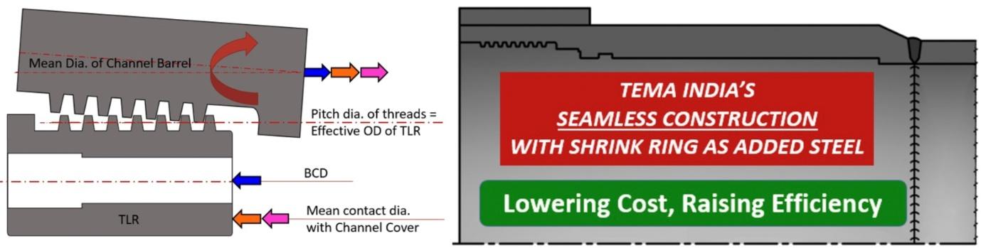
Figure 2: Bell-mouthing of threaded region of channel barrel (left), Tema India’s patented SRXTM design preventing bell-mouthing
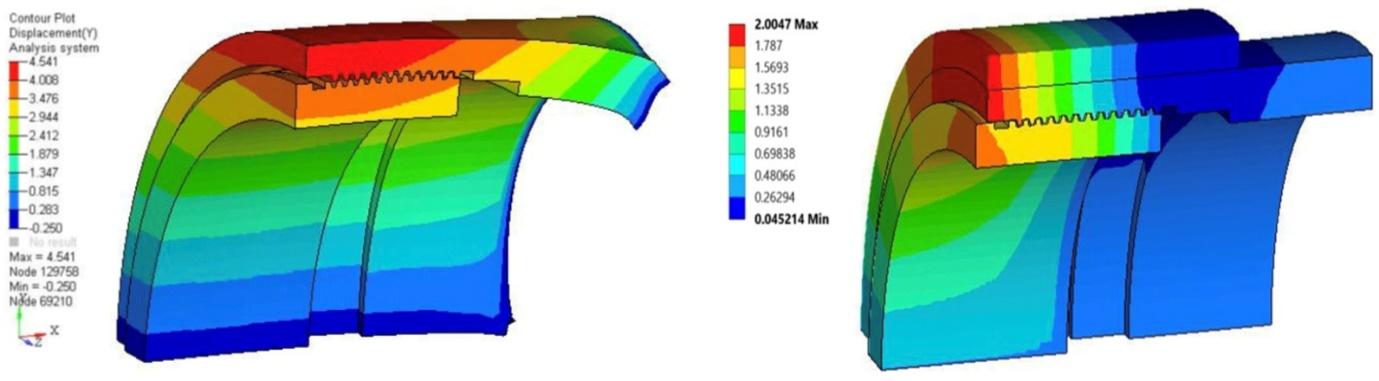
Figure 3: Displacement plot of threaded region of channel barrel: without shrink ring (left), with shrink ring (right)
Tema’s patented SRXTM technology provides the necessary local strength to the threaded region of channel barrel in form of shrink ring and prevents bell-mouthing to guarantee quick opening of the plug during critical turnarounds.
Even though the threaded closures comply with the requirements of Code, there are still problems with disassembly of the closure after hydrotest and during periodic maintenance due to bell mouthing of the channel causing jamming of screw threads. The allowable stresses for ASME Section VIII Div. 2 construction may be about 18 % higher than the allowable stress for ASME Section VIII Div. 1 construction, thereby allowing thinner sections for the same design conditions. As the thinner sections would deform more, the likelihood of jamming of the end cover could be more severe in ASME Section VIII Div. 2 constructions. With Tema’s SRXTM technology, Screw Plug exchangers can be safely constructed as per ASME Section VIII Div. 2.
Leakages
In screw-plug construction, some end users have faced leakages in areas listed below.
- External leakage at shell side gasket in Hi-Lo construction (shell flange bolted to tubesheet). The leakage can occur due to relaxation of bolting unloading the gasket, radial differential thermal expansion between tubesheet and shell flange. The chance of this leakage is greater when the Hi-Lo construction is used with high pressure on the shell side. When shell side pressure is more than 70 bar, the large diameter studs of shell flange assembled in tapped holes in tubesheet may get jammed posing difficulties in servicing and life is reduced. This problem is further worsened when round nuts are used for large diameter bolting (2.5” to 6”). To address these issues, Tema has modified the Hi-Lo design eliminating the tapped holes and round nuts as shown in image below.
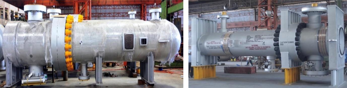
Figure 4: Hi-Lo Screw Plug Heat Exchanger: tapped bolting (left), through bolting (right)
- External leakage at tube side gasket (threaded joint of channel cover) containing the tube side pressure. This joint can leak when the equipment operates at high temperature and is subjected to cyclic service or the equipment is taken into operation after a shut-down (the bolts and gasket may get relaxed when the equipment cools during a shut-down). Generally, these leakages can be arrested by performing online tightening of outer set screws on Threaded Lock Ring.
- Internal leakage at shell side gasket in Hi-Hi construction (internal gasket joint between shell and tubesheet). The chance of this leakage is greater when shell side pressure is higher than tube side pressure or when MOC of channel is CS/ LAS and internals are of austenitic SS. The leakage can occur due to crushing of gasket, non-uniform tightening of internal set screws, or buckling of internals responsible for transmitting bolt load to gasket. Till 2005, the shell side gasket in Hi-Hi screw plugs used to be spiral wound type without inner and outer rings as specified by Licensor datasheets. In some Hi-Hi exchangers, the spiral wound gasket was found to be crushed leading to intermixing. TEMA was the first company in the world to identify the root cause and change this gasket to Kammprofile type. Today it has become a norm to use Kammprofile type gaskets for such joints.
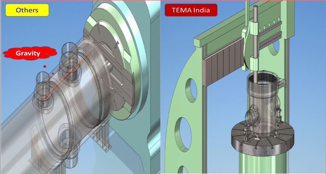
Figure 5: Machining of gasket face for shell side gasket
Due to our special machining techniques (unaffected by gravity), we achieve superior surface finish and accuracy with consistency over the entire gasket face which can perfectly seal with Kammprofile type gasket.
Preventing intermixing becoming topmost priority after BS VI
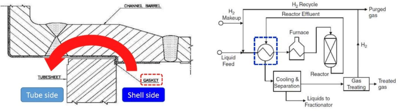
Figure 6: Intermixing of shell side fluid into tube side fluid (left), Feed-Effluent exchanger (Right)
The Hi-Hi screw-plug construction is often used in a petroleum refinery for heat exchange between the feed and effluent. In these exchangers, one side contains Sulphur-dirty feed while the other side contains Sulphur-free product (reactor effluent) which are at comparable pressures.
If the Feed-Effluent exchanger is not designed correctly, intermixing of Sulphur-free product with Sulphur-dirty feed will happen resulting into off-spec. product, compelling refineries to reprocess/ blend the product to meet the stringent BS-VI specifications.
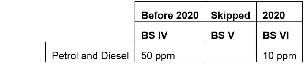
The enforcement of Bharat Stage (BS) VI emission standards in Apr-2020, drastically reduced the tolerance for Sulphur and demanded refineries to produce ultralow-sulfur fuel. Hence it has become essential to prevent even the minor intermixing which was earlier tolerable.
Some end users in India have faced severe intermixing in several Hi-Hi exchangers supplied by some manufacturers. Due to this unpleasant experience, they replaced majority of existing Hi-Hi Screw Plug (Breech Lock) exchangers with Hi-Lo construction and in new projects use of Hi-Lo construction is specified instead of Hi-Hi construction, even when pressure on shell side is high (>70 bar). However, in our opinion the Hi-Hi construction is more superior than Hi-Lo. The problem of intermixing is not attributable to the choice of Hi-Hi construction but to the fundamental design flaws with which these equipment were constructed.
Achieving leak tight joint at gasket between tube-sheet and shell has always been a nightmare for both the end-user and the manufacturer. TEMA was the first to find the perfect solution!
The external leakage causing loss of fluid containment can be easily identified by performing visual inspection of the joint. Whereas the internal leakage causing intermixing of fluids cannot be visually seen being inside the pressure containment boundary. One can assume the possibility of internal leakage from the rise in Sulphur ppm in the product stream. The extent of intermixing/ leakage can be estimated by the amount of increase in flowrate and pressure at the outlet nozzle over the inlet nozzle for the chamber in which the intermixing happens.
Bolt load transmission to shell side gasket in Hi-Hi construction
In Hi-Hi Screw Plug construction, there is an internal gasket joint between the tubesheet and main shell. This gasket seals the passage between the two compartments of the exchanger, thus preventing the shell side fluid from mixing with the tube side fluid.
The internal gasketed joint in Hi-Hi screw plug construction is very different from conventional flange joint. In conventional flange joint, the bolts are like stiff springs which generate the clamping force on gasket by getting stretched (under tension) during assembly (bolt tightening). Whereas in Hi-Hi screw plug construction, the bolts generate the gasket seating force by pushing (under compression) the tubesheet through internals like jackscrews. The bolt load is transmitted to the internal gasket at tubesheet (600-800 mm away) through the internal partition cylinder.
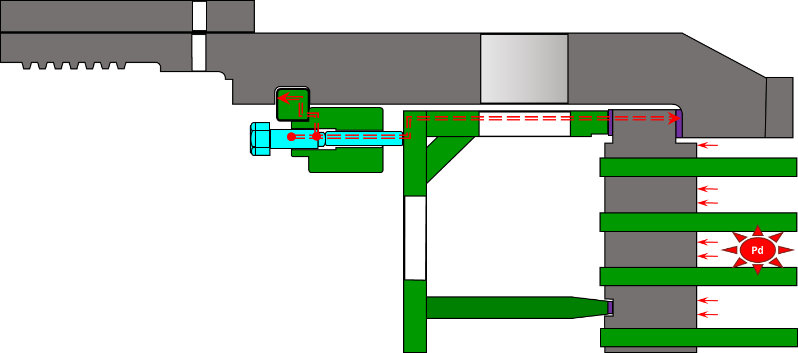
Figure 7: Loading of shell side gasket through internals
Differential thermal expansion
Due to the corrosive nature of service, the internals are generally made of corrosion resistant alloys typically austenitic stainless steels while the pressure containing body of channel barrel is made of carbon steel or low alloy steels with internal lining of stainless steel. There is a vast difference in the coefficient of thermal expansion between SS and CS/ LAS. Further, the internals are much thinner as compared to the channel barrel. Hence, internals heat and cool much faster than channel barrel during the transient conditions. This leads to a differential thermal expansion between the internals and the channel barrel. Generally, internals expand more than the channel barrel (1 to 2.5 mm).
Flexible internals were a blessing in disguise
As the internals are clamped in between the split ring and tubesheet preventing free expansion, thermal load/ stresses are induced in the internals and channel barrel. When the above differential expansion occurs, the internals deflect being thin and flexible as compared to the outer channel barrel. The push-rods which are replaceable items during overhauls are designed to buckle under excessive thermal loads to prevent damage to the equipment. This flexibility in the internals would absorb the excessive thermal loads by undergoing some deformation and thus prevent the gasket from crushing.
If the deformation of internals is elastic, the gasket remains adequately loaded maintaining the seal. However, when the internals deform plastically and the exchanger is operated with higher pressure from the shell side, the clamping load on the gasket reduces, which may cause some internal leakage i.e. intermixing between shell side and tube side fluids.
Further, the axial rigidity of internal cylinder is significantly reduced at orientation of openings for tube side inlet and outlet nozzles to allow the entry and exit of tube side fluid, while the welded pass partition plate locally increases its axial rigidity. Due to the variation in axial rigidity of internal cylinder, the shell side gasket is not uniformly compressed further increasing the possibilities of intermixing.
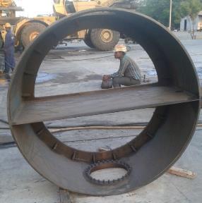
Figure 8: Openings and pass-partition plate in internal cylinder
In BS-IV era, the refineries would not mind operating the exchanger with the minor intermixing as the leakage was internal (pressure being fully contained so not hazardous situation) and the resultant product would meet the quality standards due to liberal acceptance levels for Sulphur ppm. With BS-VI imposing stringent Sulphur ppm requirements, it has become essential to prevent even the minor intermixing which was earlier tolerable.
A gasket joint can never be 100% leak-proof. However, one can design it for a desired degree of leak tightness i.e. the leakage rate is less than the acceptable leak rate. To achieve higher degree of leak tightness like 99.9%, adequate load must be transmitted to the gasket with minimum tightening losses. The gaskets must be uniformly loaded over its entire periphery to prevent leakages. To achieve this one has to make the flanges and bolts (components involved in the gasket joint) more rigid so that deflection under the above discussed thermal load is negligible, thereby preventing their deformation and resultant unloading of gasket.
The real test of this internal gasketed joint at the tubesheet is in the operating condition as thermal loads are absent during the hydrotest. Hence, exchangers supplied by some manufacturers which have successfully cleared the hydrotest have leaked in service due to these unaccounted forces.
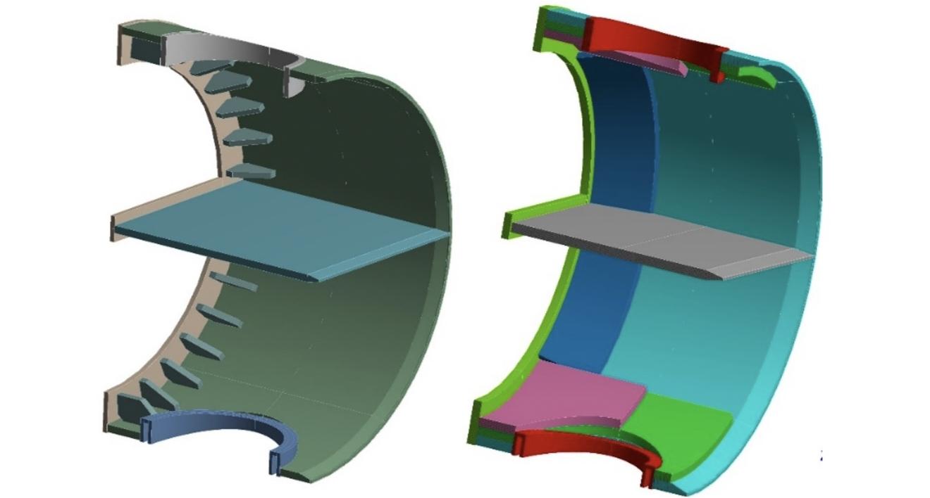
Figure 9: Typical internal cylinder (left), Internal cylinder with reinforced openings and additional stiffening to withstand axial compressive load (right)
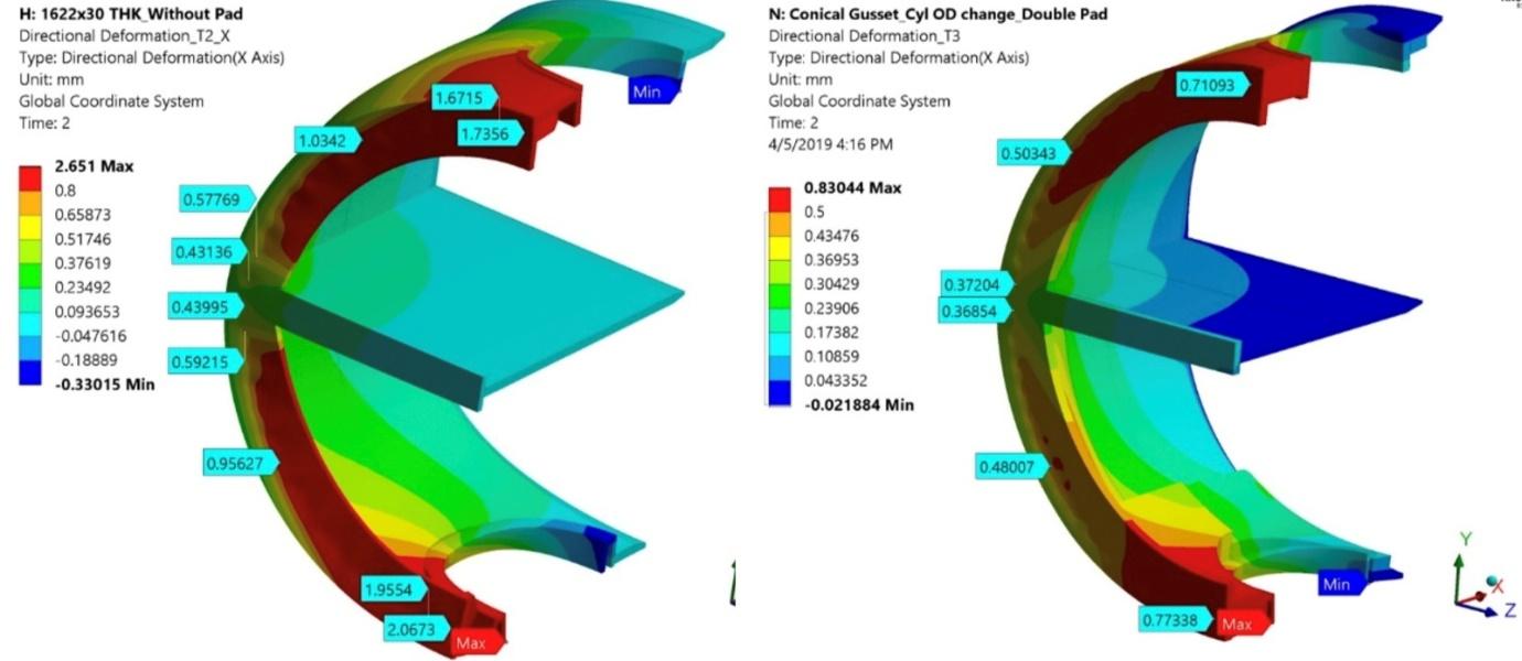
Figure 10: Axial deformation plot of unreinforced internal cylinder (left), Axial deformation plot of reinforced internal cylinder (right)
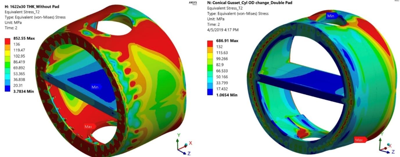
Figure 11: Stress plot of unreinforced internal cylinder (left), Stress plot of reinforced internal cylinder (right)
Consequence of having rigid internals
However, while making internals rigid one need to recognize that with reduced flexibility, the differential expansion loads will be transferred to the split ring groove in the channel barrel to which it was not exposed in the older designs with more flexible internals.
Due to the abrupt change in the section of the channel barrel at the split ring groove location, the corners of the split ring groove are high stress concentration zones. Further, the split ring groove in channel barrel is very close to the first thread on channel barrel carrying the maximum load.
The combined effect of bending of the channel barrel [bell mouthing of open end of channel] due to the hydrostatic end load on tapered threads and the differential expansion load on the split ring groove of the channel barrel would result into high levels of peak stress at the corner in the groove made to receive the split ring.
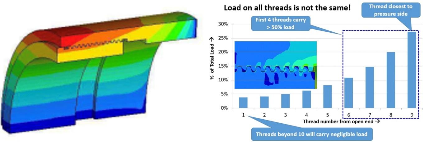
Figure 12: Bell-mouthing of open end of channel barrel (left), Uneven load distribution among ACME threads (right)

Figure 13: Split ring groove in channel barrel (left), Some manufacturers providing girth weld in channel barrel in the high stress concentration zone (right)
These heat exchangers being in hydrogen service are often subjected to PWHT. This PWHT can lead to sigma phase formation in the internal SS weld overlaid surface. Further, the cyclic secondary stresses due to varying thermal expansion of the internal cylinders during the operating cycles of the exchanger can result in development of fissures in this weld overlaid surface at the split ring groove corners. These fissures can widen up and propagate into cracks under tensile stresses caused due to bell mouthing/ bending of the threaded channel barrel end. Once the crack is set, the hydrogen in the operating fluid can diffuse in the crack leading into faster crack propagation through the entire thickness of channel barrel which may lead into catastrophic failures causing huge loss of life and property. Fortunately, no such accidents have occurred till now as no Hi-Hi exchanger with higher pressure from shell side was 99.9% leak proof due to flexible internals.
Even if the thickness of channel barrel is increased in solid construction to reduce the stress, once a crack is set in, it will propagate through entire thickness. It’s just a matter of time for a catastrophic failure to happen.
Solutions from Tema India
For getting 99.9% leak proof, safe and readily maintainable screw plug heat exchangers, the slot for split ring shall be removed, so that these fissures/ cracks are not formed or adequate reinforcement shall be provided over the split ring groove so that these fissures do not form and propagate through the channel thickness to lead to catastrophic failure.
Shrink ring extended over the split ring groove
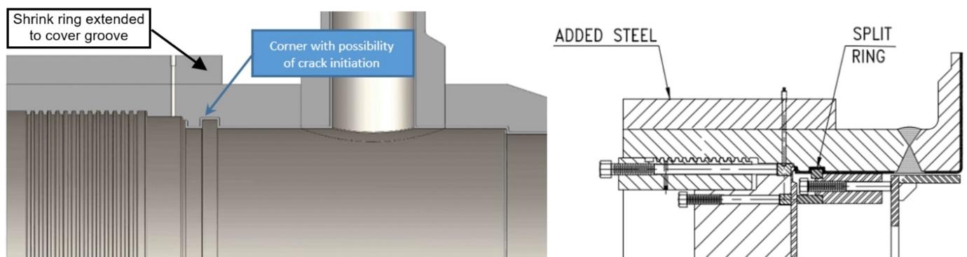
Figure 14: Modified Hi-Hi design with shrink ring extended over the split ring groove
As indicated in above figure of Tema India’s modified design, propagation of these fissures is avoided by extending shrink ring on the channel barrel up to the split ring location. This will reduce the bending/ tensile stresses at the corners of the split ring groove in the channel barrel and thereby prevent propagation of fissures into cracks can be avoided.
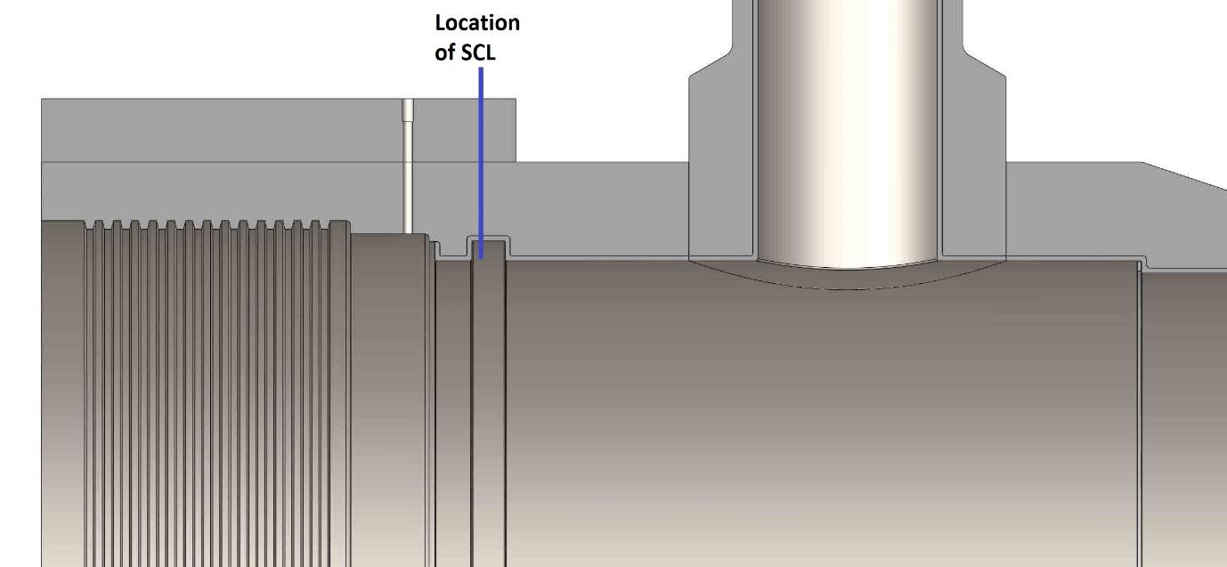
Figure 15: Stress classification line across the channel barrel thickness at the split ring groove location for the channel with reinforcement at the split ring groove location
FEA of the channel barrel with the thread closure has been carried out to compare the results of stresses induced in the channel barrel at the split ring groove location with and without metal reinforcement [shrink ring] over the split ring groove. Stress values obtained from the FEA across channel thickness at the split ring groove location are presented in table below.
| Conventional design | Shrink ring extended over the split ring groove | |
| Primary Local membrane stress [PL] | 366.17 bar | 354.7 bar |
| Primary and secondary stresses [PL+PB+Q] | 829 bar | 635.5 bar |
It is evident from the above FEA results, the bending/ total stress of the channel at the split ring groove location is reduced by 30% when the channel is reinforced with Shrink Ring at the split ring groove location.
Tema’s modified slot-free design
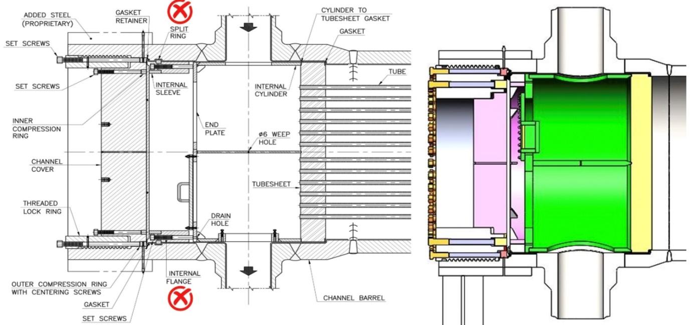
Figure 16: Hi-Hi Screw Plug construction: Conventional design (left), Tema’s modified slot-free design (right)
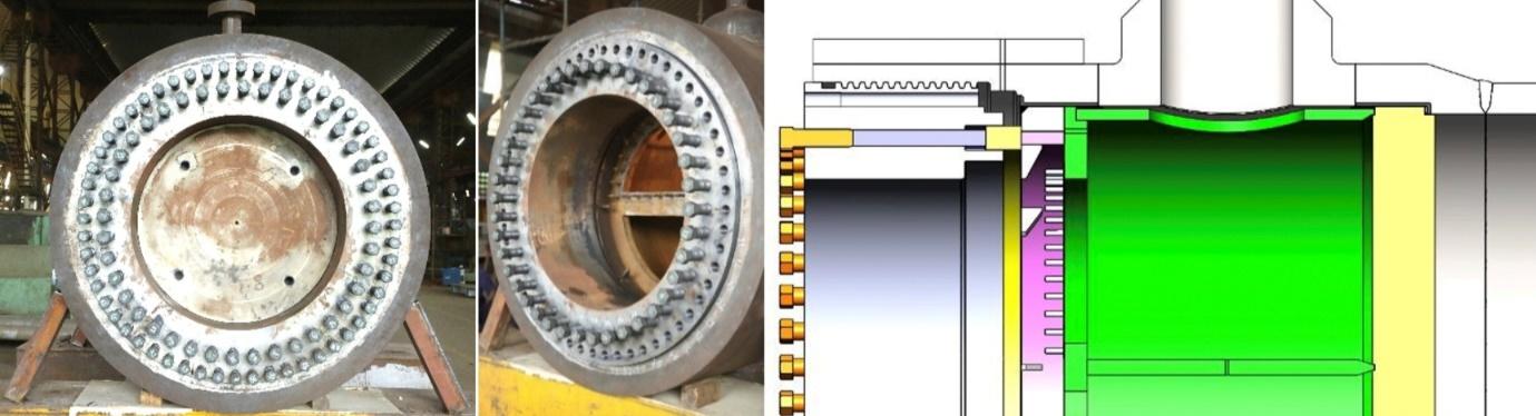
Figure 17: Full size working model of Tema’s slot-free design of Hi-Hi (left), shell side hydrotest arrangement (right)
In this design, Tema has eliminated the split ring and its groove thereby eliminating the potential risk. The new design has been validated by building a full size working model and subjecting it to hydrotest pressure. In the new design, to check the tube-to-tubesheet joints and shell side gasket joint shell side hydrotest at differential test pressure is performed by assembling the threaded lock ring without channel cover and diaphragm.
Links
ASME PVP has accepted and published our 3 technical papers.
- PVP2016-63137: An Improved Design of Threaded Closures for Screw Plug (Breech Lock) Heat Exchangers
- PVP2017-65458: Design of Threaded Closures for High Pressure Screw Plug Heat Exchangers Designed to ASME Section VIII Div. 2
- PVP2021-60974: Welding Tube to Tubesheet Joints for Corrosion Resisting Applications